The Differential Scanning Calorimeter (DSC): A Practical Guide to Oxidation Induction Time Testing
THE DIFFERENTIAL SCANNING CALORIMETER
A Practical Guide to Oxidation Induction Time Testing for Polymer Quality Assurance
1.Introduction
Look closely at the infrastructure around us, the insulation wrapped around a power cable, the pipe carrying water beneath a city street, and you find polymer compounds doing quiet, essential work for decades at a time. That kind of long service life is not automatic. It depends heavily on how well a material has been formulated to resist heat and oxygen over the years, and on whether anyone actually checked that resistance before the product left the factory.
This is where thermal analysis comes in, and specifically a technique called Differential Scanning Calorimetry, usually shortened to DSC. This article walks through what DSC actually measures, why a particular test built on it, known as Oxidation Induction Time or OIT, has become so central to polymer quality control, and what a modern benchtop DSC instrument looks like in practice. Whether you are encountering this topic for the first time or already work alongside a testing laboratory, the goal here is to make the underlying science approachable without losing technical accuracy.
It is also worth noting up front that OIT testing is not just good practice, it is written directly into Indian Standards that govern several categories of polymer products. IS 4984:2016 covers high density polyethylene pipes for water supply, while IS 15450:2004 addresses cross linked polyethylene insulated cables. Both call for an oxidation induction time procedure as part of verifying that a compound is properly stabilised, and that requirement is what a purpose built DSC instrument is designed to satisfy.
2. What a Differential Scanning Calorimeter Actually Measures
Strip away the technical language and a DSC instrument does something conceptually simple: it tracks how much heat flows into or out of a small sample as that sample is heated, cooled, or held steady at a set temperature. A few milligrams of material are placed in a metal pan, and an identical empty pan sits beside it as a reference. Both pans experience the same programmed temperature profile at the same time.
As the temperature climbs, the sample may absorb energy, for instance while melting, or release it, for instance while crystallising or breaking down chemically. The instrument constantly compares the energy needed to keep the sample pan and the reference pan at matching temperatures, and that comparison, plotted as a curve, becomes the thermal fingerprint of the material. Melting points, crystallisation behaviour, and the onset of oxidative breakdown all show up somewhere on that curve.
The word differential in the name refers to exactly this comparative approach. Rather than taking one absolute reading from the sample alone, the instrument measures the difference between two parallel readings, and that difference is what makes it sensitive enough to catch subtle thermal events that would otherwise disappear into background noise.
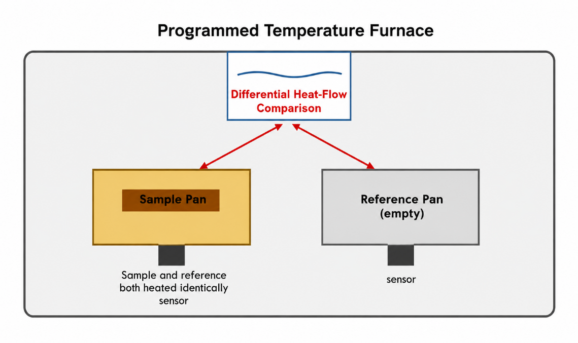
Figure 1: Basic DSC measurement principle — a sample pan and an empty reference pan are heated identically while the instrument continuously compares the heat flow to each.
3. General Applications of the Technique
Before narrowing in on Oxidation Induction Time specifically, it is worth stepping back and looking at what Differential Scanning Calorimetry is capable of more broadly as a technique. Oxidation Induction Time is simply one well known application built on top of a measurement principle that supports a much wider range of material characterisation work. The list below covers the main categories of information this kind of thermal analysis can provide.
- Characteristic temperature identification, meaning the precise temperatures at which a material undergoes a specific transition, which is useful for confirming material identity or checking consistency between batches.
- Glass transitions, the temperature range over which an amorphous material shifts from a hard, glass like state to a softer, more flexible state, an important property for polymers used in applications with varying service temperatures.
- Melting and crystallization behaviour, including the temperatures at which a material melts on heating or crystallises on cooling, which relates directly to processing conditions and end use performance.
- Heat of melting and crystallization, the quantity of energy absorbed or released during these transitions, often used to estimate the degree of crystallinity in a polymer sample.
- Solid to liquid ratio, which describes what proportion of a sample has melted at a given temperature, relevant in fields such as fats and waxes as well as certain polymer systems.
- Specific heat capacity and heat of reaction, covering how much energy a material needs to change temperature, and how much energy is released or absorbed during a chemical reaction taking place within the sample.
- Reaction kinetics and reaction behaviour, which looks at how quickly a chemical process, such as curing or crosslinking, proceeds under different temperature conditions.
- Oxidative stability and thermal stability, the broader category that includes Oxidation Induction Time testing, focused on how well a material resists breaking down when exposed to heat and oxygen over time.
This article focuses primarily on the oxidative and thermal stability category, since that is the application most directly tied to the standards discussed later. It is worth keeping the wider list in mind, however, since a single instrument built around this measurement principle can often support several of these applications depending on how it is configured and used.
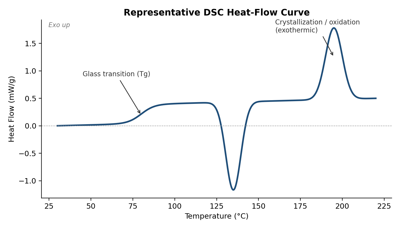
Figure 2: Representative DSC heat flow curve showing a glass transition, a melting endotherm, and a crystallization/oxidation exotherm on a single thermal scan.
4. Why Oxidation Induction Time Is the Test That Matters
Oxidation Induction Time is a specific DSC based test that answers a very practical question: how long can a polymer sample resist breaking down when it is held at a high temperature in the presence of oxygen? Every compound used in long life products like cables and pipes contains antioxidant additives whose entire job is to slow that breakdown. The OIT test is, in effect, a direct check on how well those additives are performing.
The procedure itself unfolds in two stages. First the sample is heated under nitrogen, an inert gas that will not react with the polymer, until it reaches a specified test temperature. Once that temperature has settled, the surrounding gas is switched to oxygen, and the clock starts. For as long as the antioxidant system remains active, the sample resists reacting and the heat flow trace stays essentially flat. Eventually the antioxidants are used up, the polymer begins to oxidise rapidly, and this releases heat in a sharp exothermic event visible on the graph. The time between switching to oxygen and the start of that event is the Oxidation Induction Time.
A longer OIT points to a compound with stronger long term thermal stability, while a short OIT can be an early warning of insufficient antioxidant content, a poorly balanced formulation, or degradation that already occurred during processing. Because of this, manufacturers use OIT testing both to check incoming raw materials and to confirm the quality of a finished product before it goes out the door.
5. The Standards Behind the Test
OIT testing carries real regulatory weight in India, appearing directly within the standards that govern two major categories of polymer products.
IS 4984:2016 applies to high density polyethylene pipes used for water and sewage. Under Annex B, Clause 8.5, Table 2, Serial Number iii, the standard sets out an oxidation induction time requirement as part of confirming that a pipe compound has adequate protection against thermal ageing.
IS 15450:2004 applies to cross linked polyethylene insulated cables used in power distribution. Annex H, Clauses 11.1 and 11.1.3, Table 3, defines the OIT procedure and the acceptance criteria that cable insulation compounds must meet.
Meeting the testing method described in these clauses calls for equipment capable of precise temperature control, a gas supply that can switch cleanly between an inert and an oxidising atmosphere, and heat flow measurement accurate enough to catch a well defined onset point. Those three capabilities, taken together, are the foundation of any instrument built for this purpose.
6. Inside a Modern Benchtop Instrument
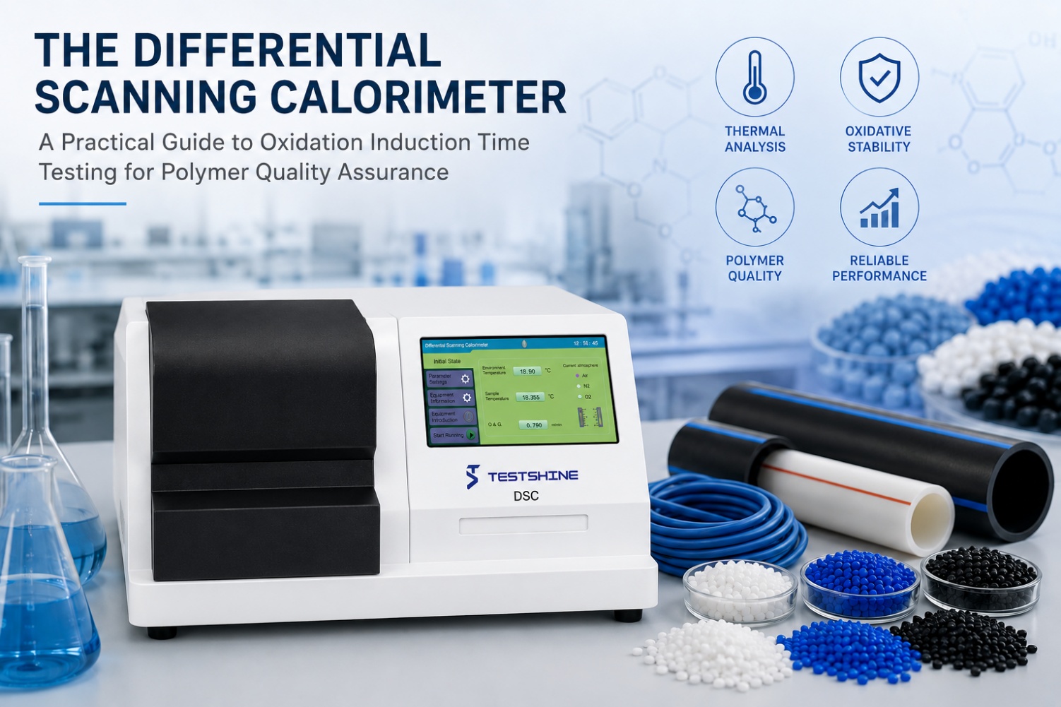
The instrument featured in this article is a compact, self contained Differential Scanning Calorimeter developed specifically to carry out oxidation induction time testing in line with IS 4984:2016 and IS 15450:2004. Its sample chamber, heating and cooling systems, gas control, and full touchscreen interface are all housed within a single unit, which removes the need for a separate external computer just to run a basic test.
The onboard touchscreen lets an operator start a run, watch the heat flow graph build in real time, and review the calculated OIT result without ever leaving the instrument. That kind of integration matters more than it might first appear, since it simplifies both installation and the day to day experience of running the equipment in a busy quality control laboratory.
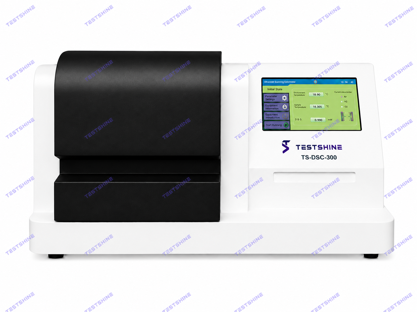
Figure 3: Simplified workflow of a benchtop DSC/OIT instrument, from nitrogen and oxygen gas supply through the sample chamber to the touchscreen display and data output.
7. What Sets This Design Apart
A handful of design decisions directly support the level of accuracy and repeatability that oxidation induction time testing demands.
- Consistent, repeatable readings across successive heating cycles, which matters when comparing OIT values between batches or against a specification limit.
- A dual chamber layout that keeps the sample pan and an empty reference pan side by side, so both experience an identical thermal environment throughout the run.
- Multiple thermocouple sensors working together to pick up very small energy changes that a single sensor design could easily miss.
- High sensitivity to both endothermic and exothermic events, covering the full range of thermal transitions a polymer sample might show.
- A build robust enough for daily industrial use while still holding onto laboratory grade sensitivity.
- Control, data acquisition, and post run processing all handled through one integrated software package, which shortens the learning curve for new operators.
8. Technical Specifications
The figures below are reproduced exactly as specified, with nothing altered, so they can be relied on as is for reference or procurement purposes.
| Display | 10 inch high resolution colour capacitive touchscreen |
| Temperature Resolution | 0.1°C |
| Temperature Accuracy | ± 0.5°C |
| Live Data Monitoring | Live data plots viewable directly on the instrument, tracking real time heat flow, temperature and time signals in dedicated modules |
| Heating Rate Range | 0.1°C to 30°C per minute, adjustable at 0.1°C intervals |
| Cooling System | Specimen chamber fan provided; cools to ambient within 15 to 20 minutes |
| Sample Pans | 100 nos. of aluminium pans provided |
| Gas Flow Control | Gas regulators and rotameters supplied for nitrogen and oxygen gas respectively |
| Data Output | Graphical view between heat flow/temperature and heat flow/timeline |
| Signal Quality | Stable, low noise, low temperature drift, solid state amplifier with appropriate sensitivities |
| Data Access | Test data accessible directly via the USB port |
| Power Supply | 230V AC, 60Hz, single phase |
9. Walking Through a Typical Test
Exact procedures follow whichever standard applies, but the general workflow stays consistent. A small sample of the polymer compound, only a few milligrams, is loaded into an aluminium pan and placed in the sample chamber next to an empty reference pan. The operator selects the target temperature called for by the relevant standard and starts the run from the touchscreen.
The chamber is purged with nitrogen first, and the sample heats at the programmed rate until it stabilises at the test temperature under that inert atmosphere. Once it is stable, the operator switches the gas supply to oxygen, which marks the beginning of the induction period. The instrument keeps recording the heat flow signal live on screen throughout. When the antioxidant system in the sample is finally exhausted, an exothermic peak appears on the trace, and the software marks the corresponding oxidation start point. The time between the switch to oxygen and that onset is reported as the OIT value, usually expressed in minutes.
Once the run finishes, results can be reviewed on the instrument itself, copied as a formatted report, or exported through the USB port for record keeping and traceability.
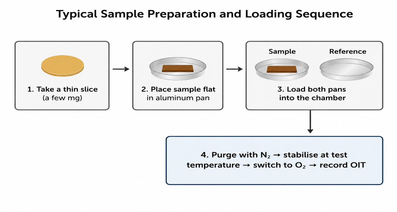
Figure 5: Typical sample preparation and loading sequence, from slicing a small specimen through purging with nitrogen, stabilising at the test temperature, and switching to oxygen to begin the OIT measurement
10. Calibration and Reference Materials
Like any thermal analysis instrument, this one needs periodic calibration to keep its readings accurate over time. Calibration is usually done using materials with well established, certified melting points, most commonly indium and tin, chosen because their melting behaviour is highly reproducible and internationally recognised as a reference.
A calibration kit containing indium and tin reference material needs to be available at the buyer's facility to carry out this procedure. Sample quantities of both materials are typically supplied for initial reference testing and calibration, giving a laboratory a starting point before it settles into its own ongoing calibration schedule.
11. Getting Ready for Installation
Because the instrument depends on a controlled gas supply and a stable electrical feed to produce accurate results, a short list of items needs to be arranged at the installation site beforehand.
- Oxygen and nitrogen gas cylinders, each fitted with an appropriate opening key or valve device compatible with the instrument's gas panel.
- A separate constant voltage stabiliser dedicated to the instrument, to keep supply fluctuations from introducing temperature variation into the measurement chamber.
- A PC or laptop with a connected printer at the buyer's end, to support data logging, report generation, and long term record storage alongside the instrument's own touchscreen interface.
Sorting these out ahead of delivery generally means the instrument can be commissioned and brought into routine use with minimal delay.
12. Where This Testing Gets Used
While this article centres on the requirements of IS 4984:2016 and IS 15450:2004, the underlying OIT method is used broadly across polymer processing. Common applications include the following.
- Verifying high density polyethylene compounds used in water supply and sewage piping systems.
- Confirming the quality of cross linked polyethylene insulation used in low and medium voltage power cables.
- Checking incoming raw materials at compounding facilities, to confirm resin and masterbatch antioxidant levels meet purchase specifications.
- Monitoring the extrusion process, since excessive heat exposure during manufacturing can deplete antioxidants and shorten OIT even before a finished product leaves the plant.
- Investigating field failures, where a product that degraded prematurely can be tested to check whether its antioxidant protection was adequate from the start.
13. Reading the Thermal Curve
It helps to understand what the heat flow curve is actually showing and how a trained operator reads it. The vertical axis typically represents heat flow, measured in milliwatts per gram, while the horizontal axis shows either temperature or elapsed time, depending on which stage of the test is being examined. During the initial nitrogen heating stage, a well behaved sample produces a fairly flat, gently sloping baseline, since no chemical reaction is taking place yet, only ordinary heating.
Once the atmosphere switches to oxygen and the induction period begins, the trace should stay close to that same flat baseline as long as the antioxidant package continues doing its job. The moment that matters most is the onset point, where the line curves sharply as the sample begins reacting with the surrounding oxygen. Software on the instrument identifies this onset by drawing a tangent line through the steepest part of the transition and extrapolating it back to the baseline; the point where the two lines meet is taken as the oxidation induction time. Because this determination depends on precise, low noise measurement, the quality of the amplifier and sensor design has a direct bearing on how consistent and defensible the reported value ends up being.
Operators also learn to watch for irregularities such as a drifting baseline or a poorly defined onset, both of which usually point to a sample preparation issue, an unstable gas flow, or an instrument fault rather than a genuine property of the material itself. Reliable equipment paired with careful, consistent technique is what produces results that can be trusted and compared across different batches or laboratories.
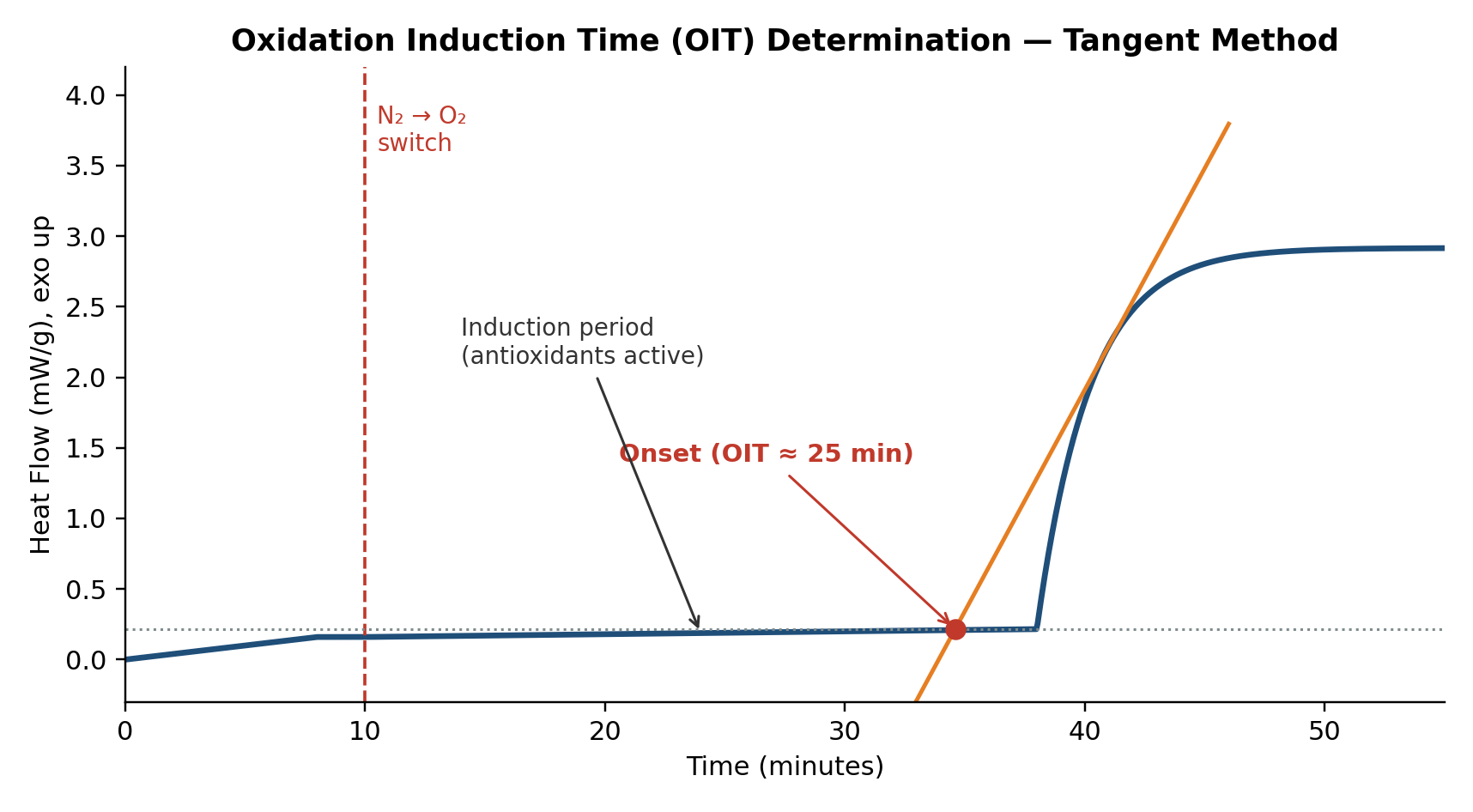
Figure 4: Oxidation Induction Time determination. After the gas switches from nitrogen to oxygen, the flat induction period ends at a sharp exothermic onset; a tangent line drawn through the steepest part of the transition is extrapolated back to the baseline to fix the reported OIT value.
14. Getting Sample Preparation Right
An OIT result is only as good as the sample preparation behind it. A few habits are widely followed in laboratories that run this test often. Sample mass is kept small and consistent, usually just a few milligrams, because a thin, evenly distributed layer inside the pan allows heat to transfer uniformly and avoids a sluggish or poorly defined thermal response.
The pan itself should sit flat against the base of the sample holder with solid thermal contact, since even a small air gap between the pan and the sensor can distort the heat flow reading. When a sample is taken from a pellet, film, or moulded part, a thin slice tends to work better than a bulk chunk, again to promote even heating. Keeping the reference pan and the sample pan consistent in type and mass also helps minimise systematic error in the differential measurement.
Gas flow rate deserves the same attention. Too slow a flow can let oxygen concentration around the sample lag behind the intended test conditions, which artificially stretches out the apparent induction time, while too fast a flow can introduce noise into the signal. Rotameters on the gas panel let an operator set and hold a steady, repeatable flow rate for both nitrogen and oxygen, supporting results that stay comparable from one test to the next.
Laboratories that run this test regularly tend to keep a written procedure covering sample mass tolerance, pan handling, gas flow settings, and calibration frequency. Lining that procedure up with the relevant standard, and periodically cross checking results against certified reference materials, is the most reliable way to build confidence in the data an instrument produces over its working life.
15. Comparing This Method with Other Thermal Techniques
Differential Scanning Calorimetry is not the only thermal analysis method available to a materials laboratory, and it helps to understand where it fits alongside two other commonly used techniques: Thermogravimetric Analysis, usually shortened to TGA, and oven ageing tests.
Thermogravimetric Analysis tracks how the mass of a sample changes as it is heated, which is useful for identifying moisture content, filler loading, or the temperature at which a material starts to decompose and lose mass. It answers a different question than DSC does. Where TGA tells you when a material starts breaking apart physically, DSC tells you about the energy changes happening inside the material, including the very early chemical signs of oxidative breakdown that occur well before any noticeable mass loss. For oxidation induction time testing specifically, DSC is the appropriate tool because the antioxidant depletion event it detects is a heat release, not a weight change.
Oven ageing tests, sometimes called long term thermal stability tests, take a different approach entirely. Rather than measuring a single controlled event in a matter of minutes, they place samples in a heated oven for days or weeks and periodically check mechanical properties such as tensile strength or elongation to see how much they have degraded. Oven ageing gives a broader picture of real world durability, but it takes far longer to produce a result. The Oxidation Induction Time test is valued precisely because it compresses that same underlying question, how well is this material protected against oxidative breakdown, into a laboratory procedure that can be completed in well under an hour, making it practical as a routine quality check rather than a lengthy research exercise.
Used together, these three techniques complement one another well. A laboratory might use TGA to confirm filler content, run OIT by DSC as a fast routine check on antioxidant performance, and reserve oven ageing for periodic, more thorough validation of a compound's long term behaviour.
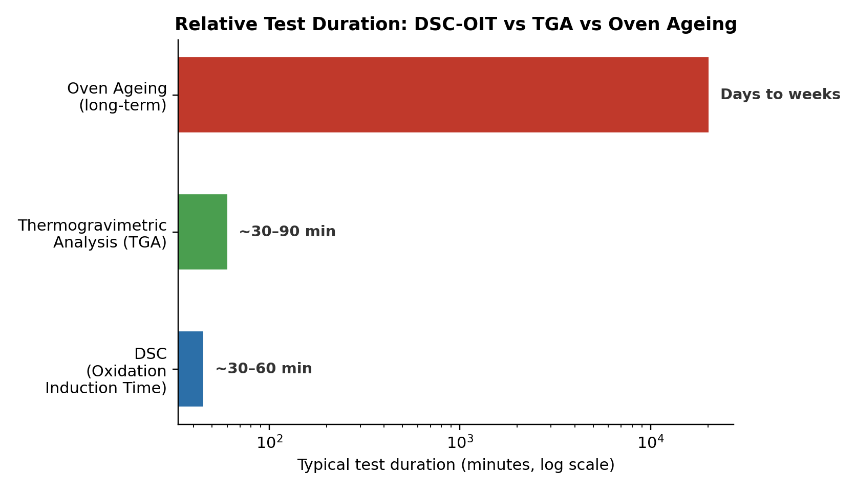
Figure 7: Relative test duration for DSC based OIT testing compared with Thermogravimetric Analysis (TGA) and oven ageing, illustrating why OIT is favoured as a fast routine quality check.
16. Safety Considerations During Testing
Working with an oxygen enriched atmosphere at elevated temperature calls for a few sensible precautions, even though the gas volumes involved in a single test are small.
- Gas cylinders should be secured upright, fitted with correct regulators, and stored away from direct heat sources or open flame, in line with standard cylinder handling practice.
- The area around the instrument should be reasonably ventilated, since a build up of oxygen in an enclosed space can increase fire risk even when no flame is present.
- Operators should avoid placing flammable materials near the gas connection panel, and should check fittings periodically for leaks using an appropriate leak detection method rather than relying on smell alone.
- Because the sample chamber reaches high temperatures during a run, operators should allow adequate cooling time before opening the chamber or handling used sample pans.
- As with any laboratory equipment, only trained personnel should operate the instrument, and a documented standard operating procedure should be available for reference.
None of these precautions are unusual for a laboratory already working with combustible gases, but they are worth stating clearly in any internal procedure so that new operators are not left to infer them on their own.
17. Data Recording, Reporting and Traceability
A test result only has value if it can be trusted later, which means good record keeping matters just as much as the test itself. Each OIT run typically generates a report that includes the sample identity, the test temperature, the gas flow rates used, the calculated induction time, and the date and operator name associated with the run.
Because the instrument allows results to be exported directly through its USB port, laboratories can build a digital archive of test reports that supports traceability back to a specific batch of raw material or a specific production run. This becomes particularly important when a customer or auditor asks for evidence that a particular lot of cable or pipe compound met its required OIT specification at the time of manufacture.
Good practice also includes retaining calibration records alongside test data, so that anyone reviewing a result later can confirm the instrument was operating within its accuracy specification at the time the test was performed. Many laboratories keep a simple logbook or digital record noting the date of each calibration check, the reference material used, and the measured melting point compared against the certified value.
18. Routine Maintenance and Long Term Care
Like any precision laboratory instrument, this equipment performs best when it receives a modest amount of regular attention rather than being left untouched between tests.
- The sample chamber should be kept clean and free of residue from previous samples, since contamination can affect the thermal contact between the pan and the sensor.
- Gas regulators and rotameters should be checked periodically for smooth operation and accurate flow readings, since a drifting rotameter can quietly affect test repeatability without being obvious from the results alone.
- The touchscreen and housing should be cleaned with a soft, dry cloth, avoiding solvents that could damage the display surface.
- Calibration should be repeated on a defined schedule, and always after any event that could affect accuracy, such as relocating the instrument or replacing a component.
- Consumables such as aluminium pans should be stored in a clean, dry environment to avoid surface contamination before use.
A short daily or weekly checklist covering these points, kept alongside the instrument, is usually enough to catch small issues before they turn into a larger problem or a batch of questionable results.
19. Frequently Asked Questions
A few questions come up often among people encountering this kind of testing for the first time, so it is worth addressing them directly.
- How much sample is actually needed for a test? Only a few milligrams, roughly the size of a small shaving or pellet fragment, since the instrument is sensitive enough to work with very small quantities.
- Why does the test use both nitrogen and oxygen rather than just air? Nitrogen creates a controlled inert environment for the initial heating stage, ensuring no oxidation begins before the test officially starts. Switching cleanly to pure oxygen at a known flow rate gives a consistent, repeatable trigger for the induction period, which ordinary air could not provide as reliably.
- How long does a typical OIT test take? Most tests are completed within thirty to sixty minutes, depending on the test temperature and how long the particular compound resists oxidation, which is considerably faster than oven ageing methods.
- Can the same instrument be used for other kinds of thermal analysis? Yes, since the underlying heat flow measurement capability supports a range of standard DSC applications, including melting point determination and crystallisation studies, in addition to oxidation induction time testing.
- What happens if a result looks unusually short or inconsistent? It is worth first checking sample preparation and gas flow settings, then confirming the instrument is within calibration, before concluding that the compound itself is genuinely under protected.
- Does ambient humidity or room temperature affect the result? A well designed sample chamber isolates the test from small changes in room conditions, though extreme swings in ambient temperature can still affect cooling times between runs and are worth accounting for in a busy laboratory schedule.
- Is it necessary to run every sample in duplicate? Many laboratories choose to run a duplicate test on a portion of their samples as an internal check on repeatability, particularly for new compound formulations or when a result sits close to a specification limit.
20. Conclusion
Differential Scanning Calorimetry remains one of the most dependable ways to find out how well a polymer compound will hold up to heat and oxygen over its service life, and the Oxidation Induction Time test built on top of it has become a standard requirement in cable and pipe manufacturing specifications. A well designed benchtop instrument brings together precise temperature control, a switchable gas atmosphere, sensitive heat flow measurement, and an integrated touchscreen interface, all inside a single compact unit built for everyday use in a working laboratory.
For any facility that needs to demonstrate compliance with IS 4984:2016 or IS 15450:2004, or that simply wants a dependable way to track the antioxidant performance of the compounds it produces or buys, this kind of instrument offers a practical, accessible route to reliable OIT data.